


Oliver Medvedik (Genspace co-founder)
Keith Comito (Life Extension Advocacy Foundation founder)
READINGS:
Bioreactors for Tissue Engineering
Design, engineering and utility of biotic games
Pac-Man of the Microscopic World
Alignment and elongation of Human Adipose-derived stem cells in reponse to direct-current electrical stimulation
Electrical stimulation systems for cardiac tissue engineering
Engineering Anatomically Shaped Human Bone Grafts
/\/\/\/\/\/\/\/\/\/\/\/\/\/\/\/\/\/\/\/\/\/\/\/\/\/\/\/\/\/\/\/\/\
LAB HOMEWORK
Build a Paramecium/Arduino interface.
Measure how fast the paramecia (a) swim and (b) change direction in response to electrical stimulation.


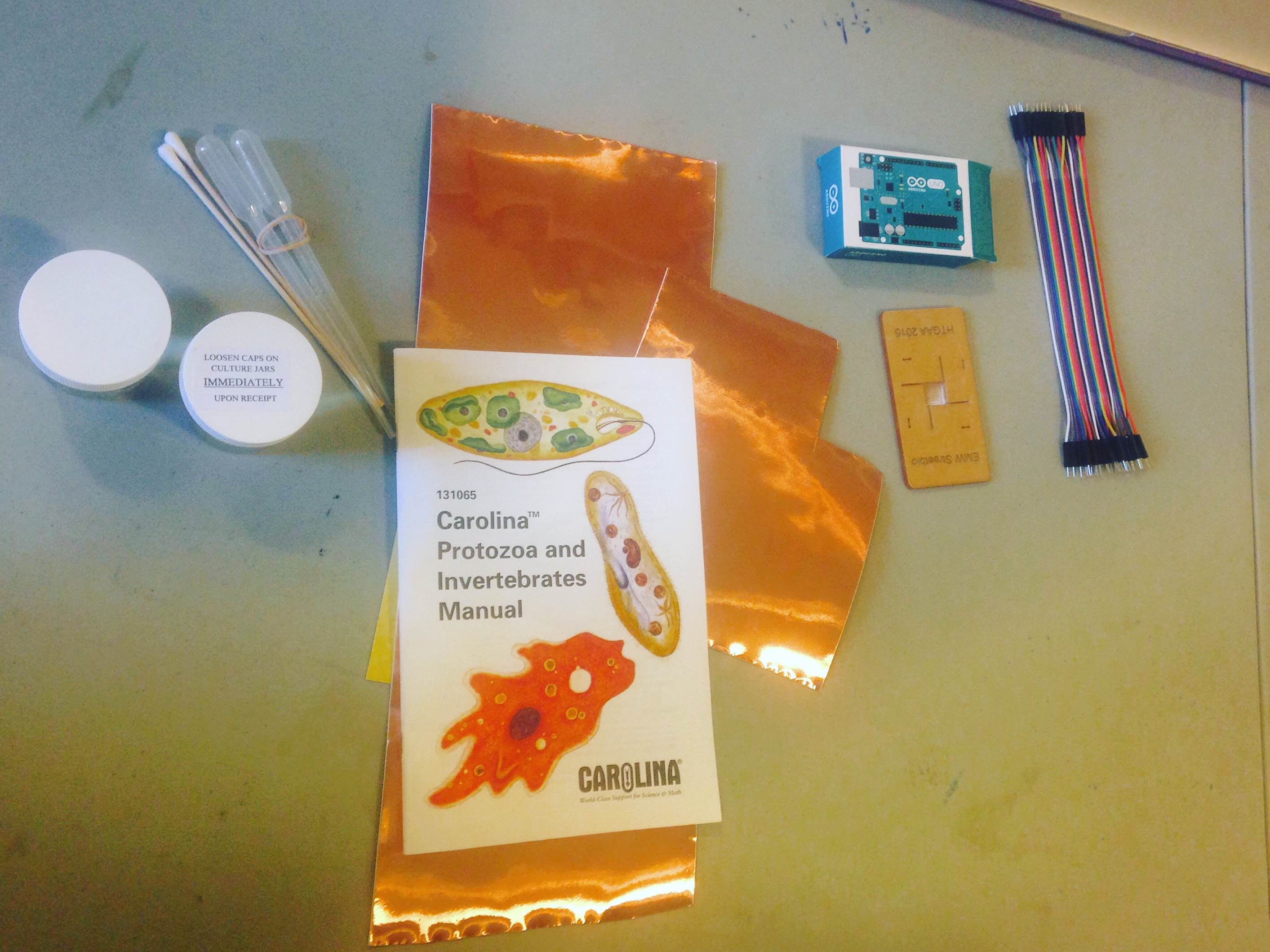


Equipment:
multimeter
laser cutter
laptop or desktop computer
standard toolbox tools: wrenches, wirecutters, screwdrivers
standard lab equipment: pipetors, tubes


References:
https://making.do/paramecium/build.html
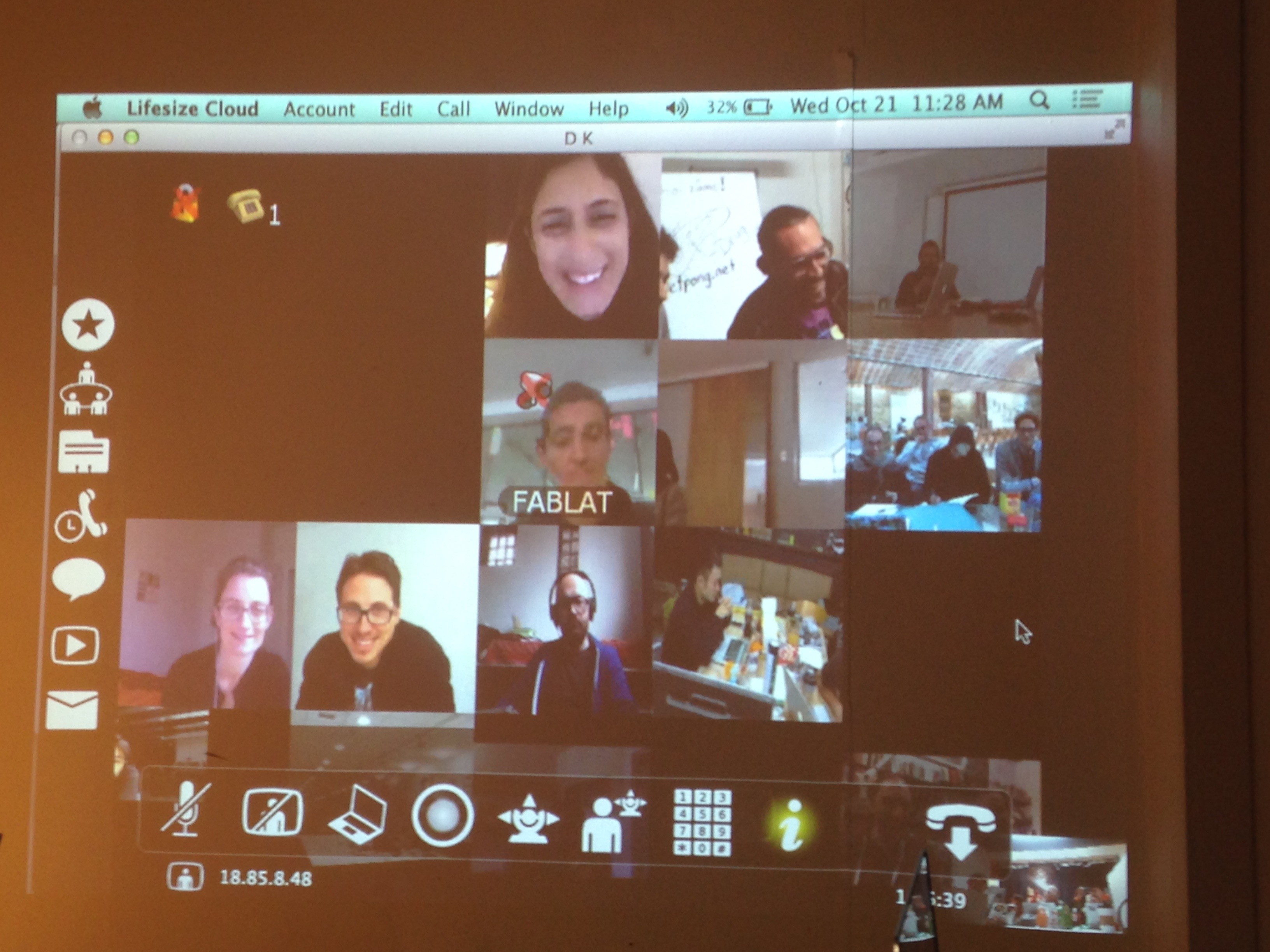
http://wetpong.net/
/\/\/\/\/\/\/\/\/\/\/\/\/\/\/\/\/\/\/\/\/\/\/\/\/\/\/\/\/\/\/\/\/\
DESIGN HOMEWORK
Problem 1: Design considerations for electrical stimulation systemsBelow appears an oscilloscope reading for a stimulus waveform from commercial stimulator. When a bioreactor is attached (pink), the stimulus waveform (blue) is no longer faithfully applied.

(a) The stimulus waveform is approximately that of a square pulse of 5V amplitude. Describe what happens to the stimulus waveform with the bioreactor attached. Refer to the figure #1 below to understand the experimental set up. When the bioreactors are attached (pink), the "stimulus waveform (blue) is no longer faithfully applied." You see the voltage drop lower compared to the "no load attached" (blue), which means you have too many bioreactors attached, or the system requires more current.
(b) Assuming there is a single impedance value for a single bioreactor can you think of an explanation for why the stimulus waveform might be distorted when connected to the load?
The single impedance value is represented by R in Ohm's Law (V = IR), where V is the voltage, I is the current and R is the resistance of a voltage loop. To achieve the voltage 5V, the current supplied to the system is not sufficient, therefore you will see distortion in the stimulus waveform.
(c) How might you expect the pink waveform to change if several of the same bioreactors were to be attached in parallel to this stimulator? Referring back to Ohm's law, the bioreactors are represented as R. So, the more bioreactors you attach, the more current you will need to supply to achieve 5V. The stimulus waveform (pink) will likely drop or distort.
(d) What recommendation for modifying the stimulator would you make to solve this problem? You can buy an amplifier that will supply additional current to the system. For future reference, to check that the current limit of the stimulation device is not surpassed by attaching the bioreactors to it, measure voltage of the source before and after the bioreactors are attached and compare waveforms.
 Diagram taken from Electrical stimulation systems for cardiac tissue engineering (Nature)
/\/\/\/\/\/\/\/\/\/\/\/\/\/\/\/\/\/\/\/\/\/\/\/\/\/\/\/\/\/\/\/\/\/\/\/\/\/\/\/\/\/\/\/\/
Problem 2: Morphological changes associated with electrical stimulation. Below appears Human adipose derived stem cells (hASCs) which were exposed to direct-current electrical stimulation for a period of 4 hours (from Tandon et al IEEE 2009).
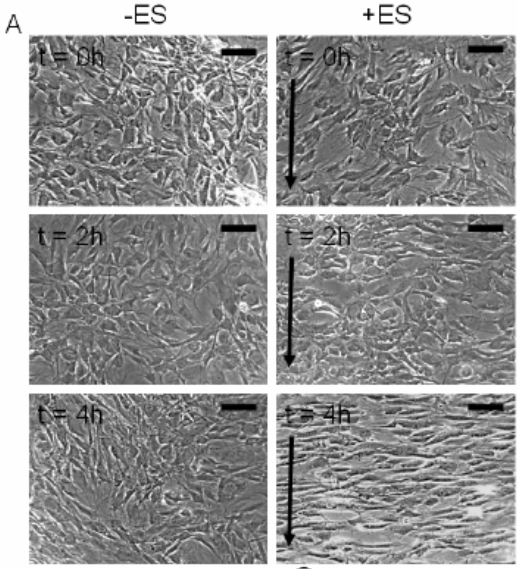
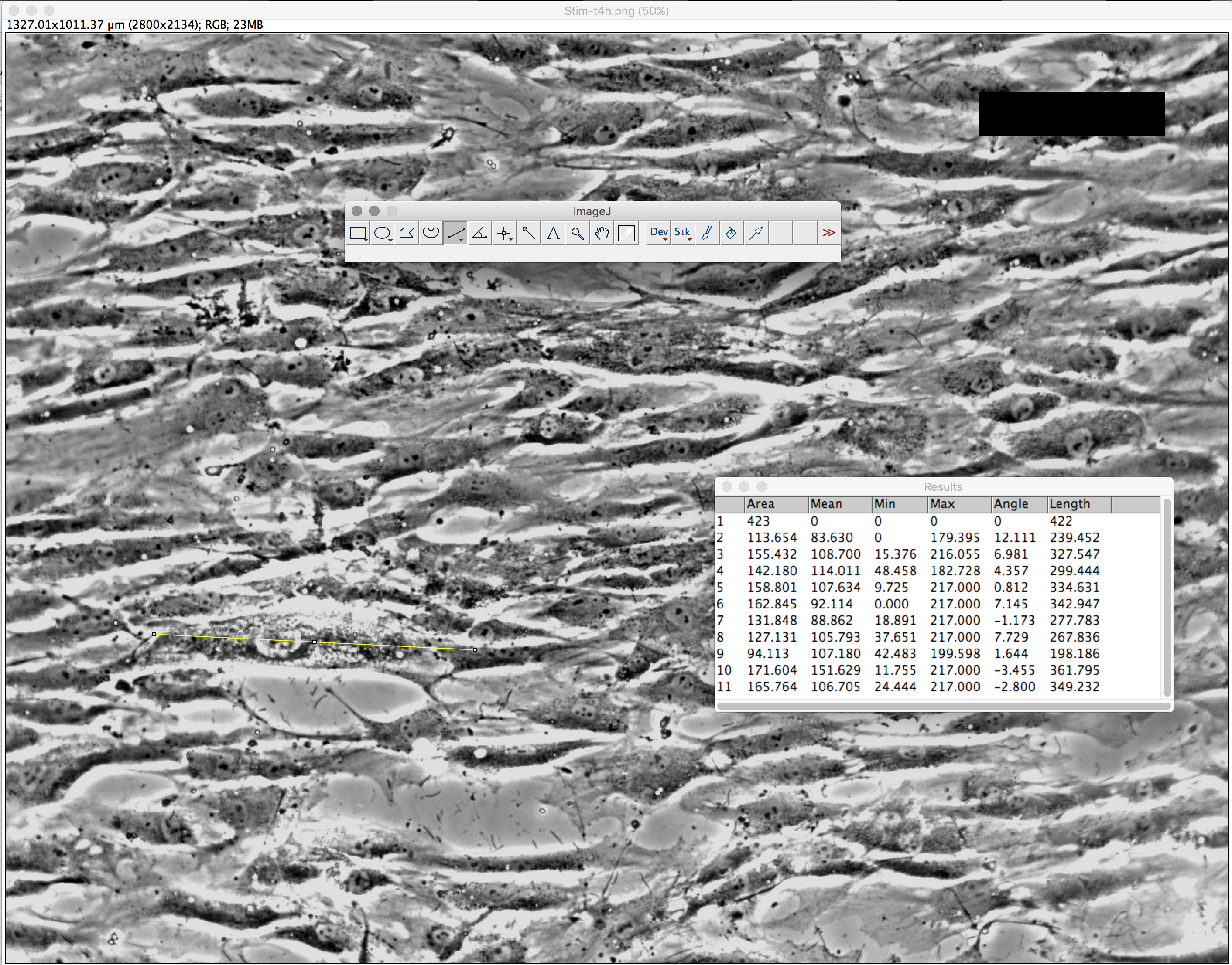
(a) Using the above images, measure and graph (1) cell length and (2) orientation angle of cells at t=0, 2 and 4 h (use any software you like, I recommend image J software available at https://imagej.nih.gov/ij/). Scale bar corresponds to 200 um and arrows delineate direction of the electric field.
To use Image J (FIJI), open cell image, change threshold color
t=0H :: Cell Length = 215.22um ; Orientation angle = -5.57 degrees
t=2H :: Cell Length = 225.01um ; Orientation angle = -4.32 degrees
t=4H :: Cell Length = 299.89um; Orientation angle = 3.34 degrees
(b) Describe the method used to identify cells (and include image captures at various stages of application of your method). State any limitations of your method, and any potential workarounds should you be able to change the experimental setup. As shown below, we took the average of 10 cells in each image (t=0, t=2, t=4) using the Image J software. A good YouTube tutorial for ImageJ: https://www.youtube.com/watch?v=8IrTXUDqmXI
(c) Given the role of mesenchymal stem cells in wound healing, state any conclusions you may draw from your above analysis. What other results would you like to see in order to support this conclusion?
/\/\/\/\/\/\/\/\/\/\/\/\/\/\/\/\/\/\/\/\/\/\/\/\/\/\/\/\/\/\/\/\/\/\/\/\/\/\/\/\/\/\/\/\/
Problem 3: design considerations for perfusion bioreactors
(a) Paraphrase in plain English the worked example on pp 1191-93 in the Ratner Biomaterials chapter. State the assumptions and approximations regarding void volume, fluid velocity, channel geometry. How might you expect these parameters to change over time during bioreactor cultivation of stem cells towards bone tissue?
(b) Now, examine the below computational models of medium flow through anatomically precise TMJ bone constructs during bioreactor cultivation(from Grayson et al 2009). (A) Color-coded velocity vectors indicate the magnitude and direction of flow through the entire construct based on experimentally measured parameters. (B) Construct is digitally sectioned, and the color-coded contours are used to indicate the magnitude of flow in the inner regions.

What is the range of velocities experienced by the cells predicted by the model, using the equations from part (a). What issues might you expect with modeling this typeof perfusion system during maturation of geometrically complicated bone tissue for 3 weeks?